What is an Inductor, and How Does it Work?
What is an Inductor?
As mentioned earlier, an inductor is nothing more than a length of insulated wire tightly wound around a magnetic core. This core can be made of ferromagnetic material, plastic, or in some cases, air (an air core). It operates based on the principle that magnetic flux develops around a current-carrying conductor.
If you’re familiar with capacitors, you’ll know that they store energy by holding equal and opposite charges on their plates. Similarly, an inductor stores energy in the form of a magnetic field that develops around it. Inductors behave differently in AC and DC circuits. But before diving into how an inductor works, let’s look at its construction and characteristics.
Structure of an Inductor
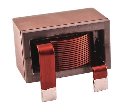
The structure of an inductor is simpler than most other components used in electronic devices. Here’s a basic guide to building a simple inductor: you only need insulated wire and a magnetic core material to wind the coil.
As shown in the image, the core is simply the material around which the wire is wound. Depending on the material used for the core, there are different types of inductors. Common core materials include iron, ferrite, etc.
In addition to core materials, inductors also come in various shapes and sizes, such as cylindrical, rod-shaped, toroidal (doughnut-shaped), and flat sheet types. On the other hand, some inductors don’t use any physical core, and these are called air-core inductors. The core plays an important role in determining the inductance of an inductor.
How Does an Inductor Work?
Let’s start with the statement that magnetic flux is generated around a current-carrying conductor. Similarly, when current flows through an inductor, it generates magnetic flux around it. In other words, the energy supplied to an inductor is stored as magnetic flux.
The direction of the flux development is opposite to the direction of current flow. As a result, an inductor resists sudden changes in the current flowing through it.
This ability is called inductance, and every inductor has a certain amount of inductance. It is denoted by the symbol L and measured in Henrys (H).
The inductance of an inductor depends on:
The shape of the coil,
The number of turns (N) in the winding,
The cross-sectional area (A) of the core,
The magnetic permeability (μ) of the core material.
The inductance is given by the formula:
L = μN2A / L
Where:
L = Inductance of the coil
μ = Permeability of the core material
A = Cross-sectional area of the coil (in square meters)
N = Number of turns in the coil
l = Average length of the coil (in meters)
Inductors in AC Circuits
As mentioned, inductors behave differently in AC circuits compared to DC. When an AC signal is applied to an inductor, it generates a magnetic field that changes over time, since the current itself is time-varying.
According to Faraday’s Law, this change in magnetic flux induces a voltage across the inductor, known as self-induced voltage (denoted as VL). In fact, the direction of this induced voltage is opposite to the direction of the changing current.
The voltage across an inductor is given by:
V L =L di / dt
Where:
VL = Self-induced voltage
di/dt = Rate of change of current over time
For example, if a 1 Ampere current changes over 1 second through a 1 Henry inductor, a 1V voltage will be induced across it. This shows how the current flowing through an inductor affects the voltage across it. The induced voltage always opposes the changing current.
V-I Characteristics of an Inductor
Let’s refer to the V-I (Voltage-Current) characteristic curve of an inductor to understand the above concepts better.
When the positive half-cycle of an AC signal passes through the inductor, the current increases. Since inductors resist changes in current, they generate an induced voltage to oppose the current that causes it.
As seen in the graph at 0°, when the current starts to increase, the induced voltage is at its maximum. Once the current reaches its peak, the induced voltage becomes negative in an attempt to prevent the current from decreasing.
This cycle repeats. From the graph, we can observe that the induced voltage in the inductor is always related to the changing current. Here, voltage and current are 90° out of phase. Therefore, in an AC circuit, the inductor continuously stores and releases energy in the form of a magnetic field.
Inductors in DC Circuits
Now that we understand how inductors work in AC, let’s examine their behavior in DC circuits.
Recall the induced voltage formula:
V L =L di / dt
When a DC source is used, the current does not change over time (di/dt = 0), meaning the induced voltage across the inductor becomes zero.
In simple terms, in a DC circuit, the inductor behaves like a regular wire, offering only the resistance of the wire itself.
However, in real circuits, the current takes a short amount of time to rise from zero to its maximum value. During this brief moment, a voltage spike is induced across the inductor. As the current rises from zero to maximum, the induced voltage is at its negative peak. Once the current reaches a stable DC level, the induced voltage rapidly drops to zero and becomes ineffective.
Thus, in DC circuits, inductors show a short-lived voltage spike and then behave like a conductor.
Inductive Reactance
Another important concept to understand is reactance, which is the resistance offered by components like capacitors and inductors to AC signals.
For inductors, this is known as inductive reactance, given by:
XL = 2πFL
From the formula, we can infer that:
Reactance increases with frequency.
Inductors resist changes in current, so they oppose high-frequency signals more strongly.
When frequency approaches zero (as in DC), the reactance becomes zero, and the inductor behaves like a conductor.