A Complete Buyer’s Guide to rectangular connector contacts: Ratings, Materials, and US Sourcing Options
In electrical and electronic assemblies, the connector contact is rarely the most visible component, but it carries a disproportionate share of responsibility for system performance. Whether you are specifying components for industrial control panels, military-grade enclosures, medical devices, or commercial automation systems, the quality and suitability of the contact inside a connector determines how reliably power and signal transfer across the interface over time.
The challenge for procurement managers, engineers, and operations teams is that connector contacts are not a commodity category where any available option performs equivalently. The material composition, mechanical design, plating finish, and current rating all interact with the application environment in ways that affect long-term reliability. Poor contact selection does not always produce immediate failure. More often, it results in gradual degradation — increased resistance, intermittent signal loss, or premature wear — problems that are expensive to diagnose and disruptive to address once a system is already in service.
This guide covers the key factors that determine contact suitability, explains the material and rating decisions buyers face, and addresses the practical realities of sourcing within the United States.
What Rectangular Connector Contacts Are and Why Specification Matters
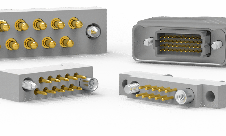
Rectangular connector contacts are the conductive elements housed within rectangular connector bodies that physically make and break electrical circuits when mated or unmated. Unlike circular connectors, which are typically associated with military and harsh-environment applications, rectangular formats are widely used across industrial, automation, power distribution, and data infrastructure environments because of their compact geometry, ease of mass termination, and compatibility with standard panel and PCB mounting configurations.
For buyers and engineers working through component selection, a well-organized resource covering rectangular connector contacts provides useful context for understanding how product categories are structured and what differentiates one contact family from another. Understanding these distinctions matters because connectors are rarely replaced in isolation. When a contact fails in a multi-position housing, the downstream effect often involves connector body replacement, re-termination of wiring harnesses, and system downtime that extends well beyond the cost of the original component.
Specification matters at the design stage because retrofitting contact types after a system is built is both costly and technically constrained. The contact must be compatible with the housing, the wire gauge used in the assembly, and the termination method — whether crimped, soldered, or insulation displacement. Getting this right from the start is the most reliable way to avoid field problems.
The Relationship Between Contact Design and Connector Performance
Contact design directly influences how well a connector performs under real operating conditions. The most important contact characteristic is its ability to maintain a stable, low-resistance connection over thousands of mating cycles and across a range of temperatures, vibration levels, and load conditions.
A contact that deforms too easily loses its spring force over time, which increases interface resistance. A contact that is too rigid may not compensate adequately for minor misalignment during mating, which can cause mechanical damage to the housing or incomplete electrical engagement. These are not edge cases — they represent the actual failure modes that field engineers encounter in preventive maintenance reviews and warranty analysis.
Contact design also affects insertion and withdrawal force, which has practical implications in high-density connectors with many positions. If individual contacts require excessive force to mate, cumulative force across a full housing can make manual assembly difficult and introduce risk of incomplete engagement in automated assembly environments.
Materials Used in Connector Contacts and Their Practical Implications
The base metal and plating used in a connector contact are the two most significant material decisions, and they are evaluated separately because they serve different functions. The base metal provides the structural and conductive foundation, while the plating layer determines corrosion resistance, contact resistance at the interface surface, and durability over repeated mating cycles.
Copper Alloys as the Standard Base Material
Copper-based alloys are the dominant base material for connector contacts across most commercial and industrial applications. Brass, phosphor bronze, and beryllium copper are the most commonly specified, each offering a different balance of conductivity, springback strength, and machinability.
Brass is cost-effective and sufficient for low-cycle, stable-environment applications where spring retention is not a critical concern. Phosphor bronze offers better fatigue resistance and maintains its spring characteristics through more mating cycles, making it appropriate for connections that are regularly engaged and disengaged. Beryllium copper sits at the top of the performance range — it has excellent conductivity, superior spring retention, and handles elevated temperatures well — but it carries both cost and regulatory considerations related to machining and disposal that buyers in some industries need to account for.
Plating Options and What They Determine
Gold plating is the established standard for low-level signal contacts where even minimal surface oxidation could increase contact resistance enough to affect data integrity. It is used in instrumentation, communications, and computing applications where signal fidelity is the primary concern. Gold does not oxidize, maintains predictable contact resistance across its service life, and tolerates low contact forces, which is important in low-insertion-force connector designs.
Tin plating is the standard choice for power contacts and general-purpose industrial connectors. It is significantly less expensive than gold and performs well in high-current applications where contact forces are sufficient to break through the oxide layer that forms over time. The concern with tin is fretting corrosion — a form of wear that occurs when vibration causes micro-motion at the contact interface, abrading the tin surface and creating resistive debris. In high-vibration environments, tin-plated contacts require careful evaluation, and some specifications call for lubrication or alternative platings to address this risk.
Silver plating occupies a middle ground. It has excellent conductivity, handles higher currents than gold at a lower material cost, and is commonly used in power distribution contacts and automotive applications. However, silver tarnishes when exposed to sulfur-containing atmospheres, which can affect contact resistance in certain industrial environments. The acceptability of silver plating depends on the specific operating environment.
Understanding Current and Voltage Ratings in Context
Current and voltage ratings published in connector datasheets represent tested performance under defined laboratory conditions, not guarantees of equivalent performance in every installation. Buyers who treat these ratings as universal maximums without accounting for application-specific factors often encounter problems that the component datasheet technically does not explain.
Derating for Real Operating Conditions
Temperature rise in a connector is cumulative. When multiple contacts in a housing are carrying current simultaneously, heat generated by each contact affects the thermal environment of adjacent contacts. Most published ratings assume a single contact carrying full rated current in isolation. When a fully populated housing operates near rated current on all positions, internal temperature rises significantly beyond what individual contact ratings suggest.
Standard engineering practice involves applying a derating factor — typically operating contacts at a percentage of their maximum rated current to ensure that the combined thermal load remains within the temperature rating of both the contacts and the housing material. The appropriate derating depends on the housing configuration, the ambient temperature of the installation environment, and whether the connector is in free air or enclosed within a panel or cabinet.
The Institute of Electrical and Electronics Engineers, through its published standards at ieee.org, provides guidance frameworks relevant to electrical connector performance in industrial applications, which procurement teams and engineers can reference when establishing internal specification criteria.
Voltage Ratings and Insulation Coordination
Voltage rating in a connector is primarily a function of the housing insulation and the spacing between contact positions, not the contact itself. However, buyers specifying contacts for replacement or cross-referencing must confirm that any alternative contact maintains the same geometric profile as the original, since even minor dimensional differences can alter the effective clearance within the housing and affect voltage withstand performance.
This is particularly relevant in high-density connectors where contact positions are closely spaced. An unauthorized substitution of a contact with a slightly different profile may clear incoming inspection but create a field reliability problem under sustained voltage stress.
US Sourcing Considerations for Connector Contacts
The sourcing environment for electronic components in the United States has become more complex over the past several years. Lead time variability, counterfeit component risk, and supply chain disruptions have shifted how procurement teams approach component sourcing, particularly for standard catalog items that were historically treated as off-the-shelf commodities.
Authorized Distribution and Traceability
For rectangular connector contacts, authorized distribution channels remain the most reliable sourcing path when traceability is a requirement. Authorized distributors receive product directly from manufacturers, maintain documented lot traceability, and typically provide certificate of conformance documentation upon request. This matters in regulated industries — defense, aerospace, medical — where counterfeit or non-conforming components carry significant liability and quality system risk.
Independent distributors and spot-market sources can provide flexibility in tight supply situations but require buyers to conduct additional incoming inspection, request test reports, and verify product markings against known-good samples. Skipping this step to reduce procurement time has been the root cause of numerous documented counterfeit component incidents across US electronics manufacturing in recent years.
Domestic Stocking and Lead Time Management
US-based distributors who maintain meaningful domestic inventory offer a practical advantage for manufacturers managing production schedules. Standard catalog connector contacts from major manufacturers are generally available with short lead times through established distribution, but specialty contacts — high-temperature ratings, custom plating, or modified contact geometry — often require longer lead times tied to manufacturing runs at overseas production facilities.
Building a buffer stock strategy for connector contacts used in high-volume or critical assemblies is a reasonable risk management approach. Contacts are small, low-cost relative to downtime risk, and have shelf lives that allow for reasonable forward stocking without significant carrying cost or obsolescence exposure.
Conclusion
Selecting rectangular connector contacts is a decision with consequences that extend well beyond the initial purchase. Material selection, plating type, current rating interpretation, and sourcing discipline all contribute to whether a connector assembly performs reliably over its intended service life or becomes a recurring maintenance issue in the field.
Buyers and engineers who invest time in understanding the technical distinctions between contact families — and who source through traceable, authorized channels — position themselves to avoid the category of avoidable failures that make up a significant share of electrical system maintenance costs in industrial and commercial operations.
The fundamentals covered in this guide provide a working framework for initial specification decisions. As applications become more specialized — higher temperatures, elevated cycle requirements, or regulated environments — deeper engagement with manufacturer technical support and independent testing resources becomes an appropriate part of the specification process.