How a Float Controlled Valve Works: A Plain-English Guide for Facility Managers
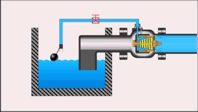
Water and fluid management in commercial and industrial facilities often comes down to the reliability of individual components. When those components fail — or behave inconsistently — the downstream effects can include equipment damage, wasted resources, or unplanned maintenance. Among the mechanisms that facility managers oversee most regularly, fluid level control systems rank high in both importance and frequency of attention. Understanding how these systems operate at a mechanical level helps managers make better decisions about maintenance schedules, component selection, and system design. This guide focuses specifically on one of the most common and consequential components in those systems.
What a Float Controlled Valve Actually Does
A float controlled valve is a self-operating mechanism that opens and closes a water or fluid supply line in direct response to the current level of liquid in a tank or reservoir. It requires no electrical input, no external signal, and no manual intervention during normal operation. The valve responds to physical changes in the fluid level, making it one of the most straightforward and dependable control systems in routine fluid management.
The core function is simple: when fluid drops below a set level, the valve opens to allow more fluid in. When the fluid rises to the target level, the valve closes to stop the supply. This cycle repeats continuously without operator involvement, which is precisely why the mechanism is relied upon in applications where consistent levels must be maintained without constant supervision.
Why Passive Mechanical Control Matters in Industrial Settings
Electrically controlled systems introduce a layer of complexity — sensors, controllers, wiring, and software all have to function correctly in sequence for the outcome to be reliable. A mechanical float system removes most of that dependency. The control logic is embedded in the physical relationship between the float and the valve linkage itself. If the float rises, the valve closes. If it falls, the valve opens. There is no signal chain that can be interrupted, no software that can misread a sensor, and no controller that can go offline.
For facility managers responsible for cooling towers, storage tanks, livestock watering systems, irrigation holding tanks, or boiler make-up water systems, this matters because reliability in those environments is non-negotiable. Downtime caused by a failed electronic control is not always predictable and is rarely inexpensive. A well-maintained mechanical float system, by contrast, fails in ways that are visible and straightforward to diagnose.
The Mechanical Components and How They Interact
The operating principle of a float controlled valve depends on a small number of physical parts working together. Each component has a defined role, and understanding those roles individually helps clarify how the system functions as a whole and where problems typically originate.
The Float
The float is a buoyant object — typically spherical — that sits on the surface of the liquid in a tank. As the liquid level changes, the float moves with it. That movement is the mechanical input that drives the rest of the system. The float itself does no controlling; it simply responds to the fluid surface and transmits that positional information through a connected arm or linkage.
Float material selection is relevant in facility management because the fluid being controlled determines what the float must be made of. Water at moderate temperatures allows for a wide range of materials. Corrosive fluids, high-temperature systems, or food-grade environments each impose different requirements. Floats made from stainless steel are commonly used in industrial applications where plastic would degrade or corrode over time. The float’s ability to remain buoyant and structurally intact over long periods is foundational to the system’s reliability.
The Arm and Linkage
Connected to the float is a rigid arm that pivots around a fixed point. As the float rises or falls, the arm rotates around that pivot. The opposite end of the arm connects to the valve mechanism itself. This lever arrangement translates the vertical movement of the float into a mechanical force applied to the valve. The geometry of the arm determines how sensitive the valve is to changes in fluid level and how much force is available to open or close the valve against supply pressure.
In older or more basic systems, this arm is a simple rod connected directly to the valve stem. In more sophisticated configurations, the linkage may include adjustable settings that allow the activation point to be tuned — meaning the level at which the valve opens or closes can be calibrated without replacing components. This adjustability matters in facilities where process requirements change or where initial installation conditions were not ideal.
The Valve Body and Seat
The valve body houses the moving parts that actually control fluid flow. A plug or diaphragm inside the valve body seats against an opening — the valve seat — to block flow when closed. When the float drops and the arm pulls or pushes the plug away from the seat, fluid flows through. When the float rises and the arm returns the plug to the seated position, flow stops.
The design of the valve seat and the material of the sealing element determine how completely flow is stopped and how long that seal holds up under repeated cycling. In high-use applications, the sealing components wear over time, which leads to slow leaks or incomplete shutoff. Identifying this pattern early — typically through elevated water consumption or tank overfilling — allows for targeted maintenance rather than reactive emergency repair.
Where Float Controlled Valves Are Typically Used
These valves appear across a wide range of facility types, often in places that receive little day-to-day attention because they are expected to operate without intervention. Understanding common applications helps facility managers recognize when a system they manage relies on this mechanism, even if it was never labeled as such.
• Cooling tower make-up water systems, where consistent basin water levels directly affect thermal performance and equipment protection
• Above-ground and underground storage tanks used for fire suppression water supply, where level maintenance is a safety compliance requirement
• Agricultural and livestock watering troughs, where the simplicity of the mechanism makes it well-suited to remote or low-maintenance environments
• Boiler feed water holding tanks, where fluctuating supply could affect system pressure and energy efficiency
• Swimming pool water management systems, where evaporation and backwash cycles regularly reduce water levels
• Chemical process tanks in manufacturing, where the valve material must be compatible with the fluid being controlled
In each of these settings, the float controlled valve performs the same fundamental function. What differs is the operating environment, the fluid characteristics, and the consequences of failure. A malfunctioning valve in a cooling tower basin causes a different class of problem than one failing in a livestock trough, but the underlying mechanical failure is often identical.
Common Failure Modes and What They Indicate
Float controlled valves are durable, but they are not immune to wear. Recognizing the signs of a failing valve before it causes operational disruption is one of the more practical skills a facility manager can develop around this type of equipment. According to general guidance from bodies such as the U.S. Environmental Protection Agency, undetected water system leaks and equipment malfunctions in commercial facilities are a significant source of unnecessary water consumption.
Continuous Overflow
When a float controlled valve fails to close at the appropriate level, the tank overfills and water exits through the overflow outlet continuously. This is usually caused by one of three conditions: the float has become waterlogged and sunk to a point where it no longer rises with the water surface; the valve seat has worn and no longer seals properly; or the arm linkage has become disconnected or bent, preventing full valve closure. Each cause requires a different corrective action, but all are diagnosable through visual inspection during operation.
Failure to Open or Fill Slowly
If a tank is not refilling at the expected rate, the valve may be partially obstructed by sediment or mineral deposits, particularly in areas with hard water. The float arm may also be restricted in its movement by corrosion or debris. Slow fill rates in critical systems — fire water storage being one example — can create compliance and safety exposure that facility managers need to address promptly.
Chatter or Repeated Cycling
In some installations, a float controlled valve will open and close repeatedly in short intervals rather than operating in clean, distinct cycles. This behavior, sometimes called hunting or chatter, typically occurs when the float is positioned too close to the valve activation threshold due to incorrect arm adjustment, or when the incoming supply pressure is higher than the valve is rated for. Over time, this repeated cycling accelerates wear on the sealing components and shortens the service life of the valve significantly.
Maintenance Considerations for Facility Management Teams
The relative simplicity of a float controlled valve system means that most maintenance tasks are within the capability of in-house facility staff, provided the system is accessible and parts are available. Effective maintenance centers on scheduled inspection rather than reactive repair.
Inspection intervals should account for the operating environment. A valve managing clean, treated municipal water in a moderate temperature range will cycle through many years of service before requiring component replacement. A valve managing untreated well water or process fluids in a high-temperature or corrosive environment may need attention considerably sooner. Calibrating inspection schedules to actual operating conditions — rather than applying a generic timeline — reduces both the cost of over-maintenance and the risk of under-maintenance.
When components do require replacement, the float itself and the valve’s internal sealing elements are the most frequent candidates. Both are generally available as spare parts and can be replaced without removing the entire valve assembly in most configurations. Keeping a small stock of these components on-site reduces response time when a failure does occur.
Closing Considerations for Facility Managers
A float controlled valve is not a complex device, but it carries significant operational weight in the systems it serves. Its value lies in the fact that it operates continuously, without requiring human input or electronic infrastructure, to maintain a condition that many facility systems depend on. When it works correctly, it goes unnoticed. When it fails, the effects are often visible quickly — through overflow, low levels, or unusual water consumption patterns.
For facility managers, the most practical approach is to treat these valves as components that deserve periodic, structured attention rather than reactive repair. Understanding how the mechanism works, recognizing the early indicators of wear, and maintaining a clear record of where float-operated systems exist within a facility all contribute to more consistent and cost-controlled operations. The simplicity of the design is an asset, but it does not eliminate the need for informed oversight. Knowing what to look for — and why — is what converts that simplicity into long-term reliability.