Draft Angle Calculation: From Material Shrinkage to Optimal Mold Design
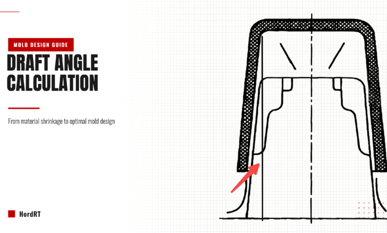
Draft isn’t decorative tilt added to make a part look tapered. It’s what physically lets a molded part separate from the steel that shaped it. Get the draft wrong and the result isn’t subtle: stuck parts, drag marks across a surface that was supposed to be cosmetic, longer cycles as operators wait for parts to release, and tooling wear that accelerates with every cycle that fights the geometry instead of working with it.
This guide walks through why shrinkage drives draft requirements, what the data says about how much draft different materials actually need, and the one calculation (texture plus draft) that causes the most expensive mold redesigns when it’s skipped.
The Shrinkage Connection
Plastic shrinks as it cools from melt temperature to room temperature. As plastic cools, shrinkage creates additional contact pressure between the molded part and the core surface, increasing resistance during ejection. Draft is designed to reduce this resistance by gradually separating the molded surface from the tool during ejection.
Semi-Crystalline Materials Need More Draft
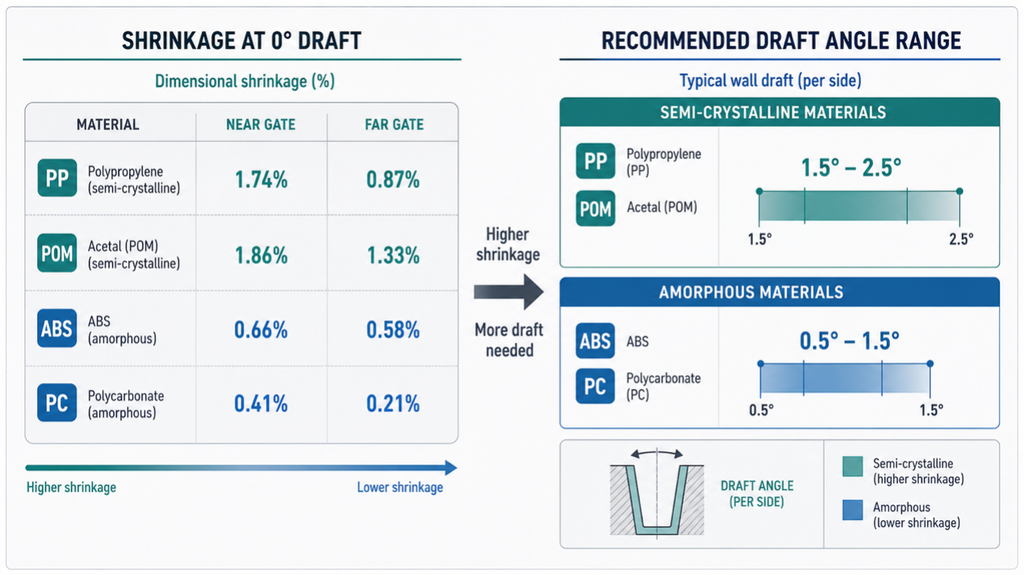
Semi-crystalline polymers like PP and POM form ordered molecular structures as they cool, which produces both higher shrinkage and more pronounced grip on the core. A controlled academic study molding identical geometries in PP, POM, ABS, and PC measured, at a 0° draft angle, shrinkage of 1.74% near the gate and 0.87% far from the gate for PP, and 1.86% near-gate versus 1.33% far-gate for POM [1]. That’s roughly two to four times the shrinkage measured for the amorphous materials in the same study and at the same draft condition.
Amorphous Materials Need Less, But Still Need Some
The same study measured ABS shrinkage at 0.66% near-gate and 0.58% far-gate, and PC at just 0.41% near-gate and 0.21% far-gate, also at 0° draft [1], confirming that amorphous polymers solidify with far less volumetric change because their molecular chains never form the ordered crystalline structure that drives semi-crystalline shrinkage. Lower shrinkage means less grip on the core, but it doesn’t mean zero draft is acceptable. Even PC parts in the study showed measurable demolding-related surface effects at insufficient draft angles.
Glass Fiber Changes the Picture Again
Adding glass fiber reduces shrinkage but doesn’t eliminate the need for draft. A 30%-glass-filled PA6 datasheet shows molding shrinkage of just 0.2% parallel to flow versus 0.7% normal to flow, a more than 3x difference between directions on the same part. That anisotropy means draft and ejection design for glass-filled parts has to account for direction, not just magnitude.
Measured shrinkage by material (same test geometry, at 0° draft)[1]
| Material | Crystallinity | Near-gate shrinkage | Far-gate shrinkage |
|---|---|---|---|
| PP | Semi-crystalline | 1.74% | 0.87% |
| POM | Semi-crystalline | 1.86% | 1.33% |
| ABS | Amorphous | 0.66% | 0.58% |
| PC | Amorphous | 0.41% | 0.21% |
Note: Shrinkage values vary depending on resin grade, part geometry, wall thickness, mold temperature, processing conditions, and fiber orientation. These values are from a controlled study and should be used for comparison rather than as universal design values.
Standard Draft Rules by Material Type
Draft requirements scale with the shrinkage behavior above, and the same academic study translated its measurements into practical draft ranges.
Practical Ranges for Semi-Crystalline Materials
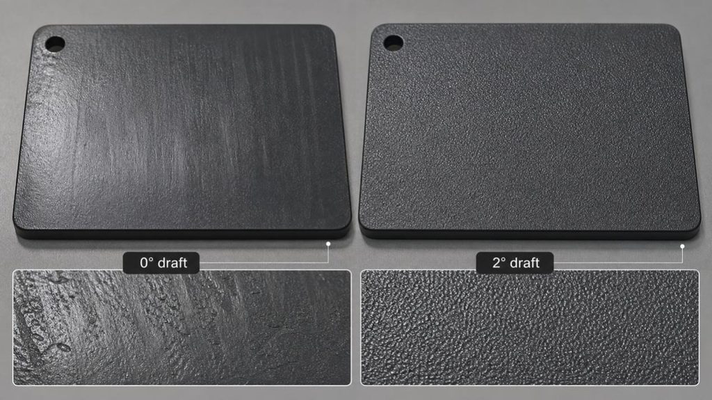
For PP and POM, the study recommends draft angles of roughly 1.5° to 2.5° to reduce demolding friction and bring near-gate and far-gate surface consistency into line [1]. Below that range, the study measured texture replication differences exceeding 50% between the near-gate and far-gate regions of the same PP part at 0° draft, dropping below 10% once draft exceeded 2° [1]. That’s not a small effect. It’s the difference between a part that looks uniform and one that visibly varies across its own surface.
Practical Ranges for Amorphous Materials
For ABS and PC, the same research recommends roughly 0.5° to 1.5° of draft, with more of the surface-quality outcome depending on mold finish and stable filling pressure than on draft angle itself [1]. Amorphous materials are more forgiving on draft magnitude, but they’re not draft-free, and the study still recorded localized texture and shrinkage inconsistencies at the lowest angles tested.
Where to Add Extra Draft Regardless of Material
Deep features and sliding cores experience more cumulative friction over their length than a shallow feature does, so they generally warrant added draft beyond a part’s baseline angle. Transparent and high-gloss surfaces also tend to need more draft than the same geometry in an opaque, textured finish, since any drag mark is far more visible without a texture to mask it.
Texture × Draft: The Critical Calculation
Surface texture and draft angle interact in a way that catches many design teams off guard, because the interaction isn’t visible until parts are already being molded.
Why Texture Multiplies the Draft Requirement
A textured cavity surface has microscopic peaks and valleys that grip a part far more aggressively during ejection than a polished surface does. The deeper the texture, the more draft is needed to let the part release without dragging across those peaks and tearing or polishing them smooth, which destroys the intended finish. The same study that measured draft-versus-shrinkage also found that draft angle’s effect on near-gate-to-far-gate texture consistency was most pronounced for the more aggressively textured, higher-shrinkage materials, where insufficient draft produced a measurable mismatch in how clearly the texture replicated at different points on the same part [1].
Why This Is the Most Expensive DFM Mistake to Discover Late
Draft angle decisions made before texture selection often don’t account for the texture that gets specified afterward. If a mold is cut with draft sized for a smooth, untextured finish and the project later adds a heavy texture, the existing draft is very likely insufficient. Re-cutting cavities to add draft after a mold exists is a far more expensive fix than specifying the right draft angle before the first cut.
Feature-Specific Direction and Practical Defaults
Getting the Direction Right, Not Just the Magnitude
Draft direction matters as much as draft magnitude. External faces should draft toward the parting line so the part releases cleanly from the cavity side; internal cores should draft away from the core so the part releases from the core side without pulling material back into an undercut. Getting the direction backward creates an undercut, and an undercut means the mold physically cannot open without breaking the part or the tool.
Verifying Every Surface, Not Just the Obvious Ones
It’s common to draft the main visible walls of a part correctly while missing a smaller feature, a boss, or a rib that was added late in the design process. Every surface that contacts the mold needs its own draft check; a single missed feature can be enough to prevent clean ejection even when the rest of the part is drafted correctly.
DFM Best Practices for Draft
- Input draft into the CAD model from the very first design pass, not as a late addition
- Select draft angle based on the actual material’s crystallinity and shrinkage behavior, not a single generic default across every project
- Recalculate draft requirements immediately after any texture is added or changed
- Verify draft direction on every individual surface, not only the primary part walls
- Treat surface finish and texture requirements as inputs that drive draft angle, rather than adding draft as an afterthought once finish is decided
Getting Draft Right Before Steel Is Cut
A mold maker that catches draft problems on screen, before any steel is cut, avoids the cost of re-polishing, re-cutting cavities, or removing a texture that was specified without enough draft to support it. HordRT performs draft analysis per feature as part of its DFM review during tool design, within its injection molding services, specifically to catch insufficient draft before it becomes a steel problem rather than a CAD problem. The honest caveat: DFM review can catch insufficient draft, but it can’t retroactively fix a part geometry that has genuine undercuts baked into its design intent; those still require a design change, a slide, or a lifter, which adds tooling cost regardless of how early the issue is caught.
Conclusion
Draft angle is cheap to get right in CAD and expensive to fix in steel. Size it to the material’s actual shrinkage and crystallinity, not a single rule applied to every project. Recalculate it the moment texture enters the conversation, and verify direction on every surface, not just the obvious ones. Get those habits in place early, and ejection problems become a rare exception instead of a recurring fight on the production floor